Claim
An Elevated Evacuated Tube can be supported at altitudes of up to 15km by electrically powered lift fans supplied with power from the ground.
Evidence
An Elevated Evacuated Tube (EET) is a lightweight, vacuum-tube segment that extends the protected zero-drag flight corridor through the densest part of the atmosphere, so that the vehicle exits into the free atmosphere at an altitude of 15 km. This configuration reduces the peak aerodynamic load and heating on the vehicle during its transition to open air and moves the resulting sonic boom to a much higher altitude, greatly reducing its impact on the ground and minimizing disturbance to populated areas.
The EET does not support the spacecraft's weight; rather, it is designed to remain centered on the spacecraft's ballistic flight path. The section of the EET nearest the ramp is engineered to support the weight of the launch sled and its guideway, as the launch sled detaches from the spacecraft at the end of the ramp and then decelerates against the guideway while inside the first part of the elevated evacuated tube.
The EET operates as an aeronautically supported structure, held aloft by numerous lift nacelles powered from the ground via high-voltage direct current (HVDC) transmission. Its internal radius is set by the vehicle radius plus some additional margin for station-keeping:
For reference, the diameter of an Airbus A300 is 5.64 m, giving it a radius of 2.82 m.

The evacuated interior provides a zero-drag path for the spacecraft, while the external shell must withstand atmospheric pressure varying from approximately 62 kPa at 4 km to 12 kPa at 15 km. To resist this differential pressure efficiently, the tube is constructed as a stiffened shell using frames, formers, and stringers similar to those used in modern aircraft fuselages.
Assuming an average skin thickness of , aluminum-lithium alloy density , and an external radius , the skin mass per meter is estimated as:
Including internal stiffeners and joint structures adds roughly 50%, giving an estimated total structural mass per meter of:
This design can maintain structural stability against buckling under the maximum external pressure of 62 kPa while providing a safety margin sufficient for operational gust loads.
Because the tube is evacuated, it experiences a small buoyant lift equal to the weight of the displaced air:
At 15 km, where , this corresponds to about of buoyant relief, whereas at 4 km, where , this corresponds to about . While this offsets only a small fraction of the structural mass, it is nevertheless included for completeness.
The tube is supported aeronautically by gimballed lift nacelles, which are attached to the tube by struts, each housing an electric motor driving a high-altitude propeller optimized for low-density operation. The nacelles provide both vertical lift and attitude control through thrust vectoring. Power for the lift fans is transmitted from the ground through HVDC cables integrated along the structure.
Lift Generation
The lift fans' performance is characterized by their thrust-to-weight ratio (in N/kg) and by the power consumed per Newton of thrust generated (in W/N). As the individual lift fans will spend most of their operational time on station, their rotors will be optimized for maximum efficiency at their on-station altitude. In other words, changes in air density are handled by varying rotor sizing rather than by using a single rotor design and accepting non-uniform performance across operational altitudes. For example, the rotors designed to operate at the lowest altitudes will be engineered more like those of an eVTOL aircraft, while the rotors optimized for the highest altitudes will tend to resemble the large rotors used on the Mars Ingenuity helicopter. These rotors need to generate sufficient lift across all operational altitudes, from the EET hangar altitude to the fully deployed altitude of 15 km, but since they will spend most of their time at the fully deployed altitude, their efficiency in this flight regime is given priority.
For example, the Ingenuity helicopter draws 350 Watts when flying and generates more than enough thrust to lift itself off the surface of Mars. Its mass is 1.8kg and on Mars the acceleration of gravity is 3.73 m/s²; therefore, its propulsion system generates 1.8kg×3.73m/s² = 6.7N of thrust. It's power per unit of thrust is 350/6.7 = 52 W/N. A modern drone motor, such as the A45 brushless drone motor can generate a maximum pulling force of 52 kg while drawing 4100 W, which is only 4100/(52*9.81) = 8 W/N. From public databases we can determine the relationship between power and thrust.
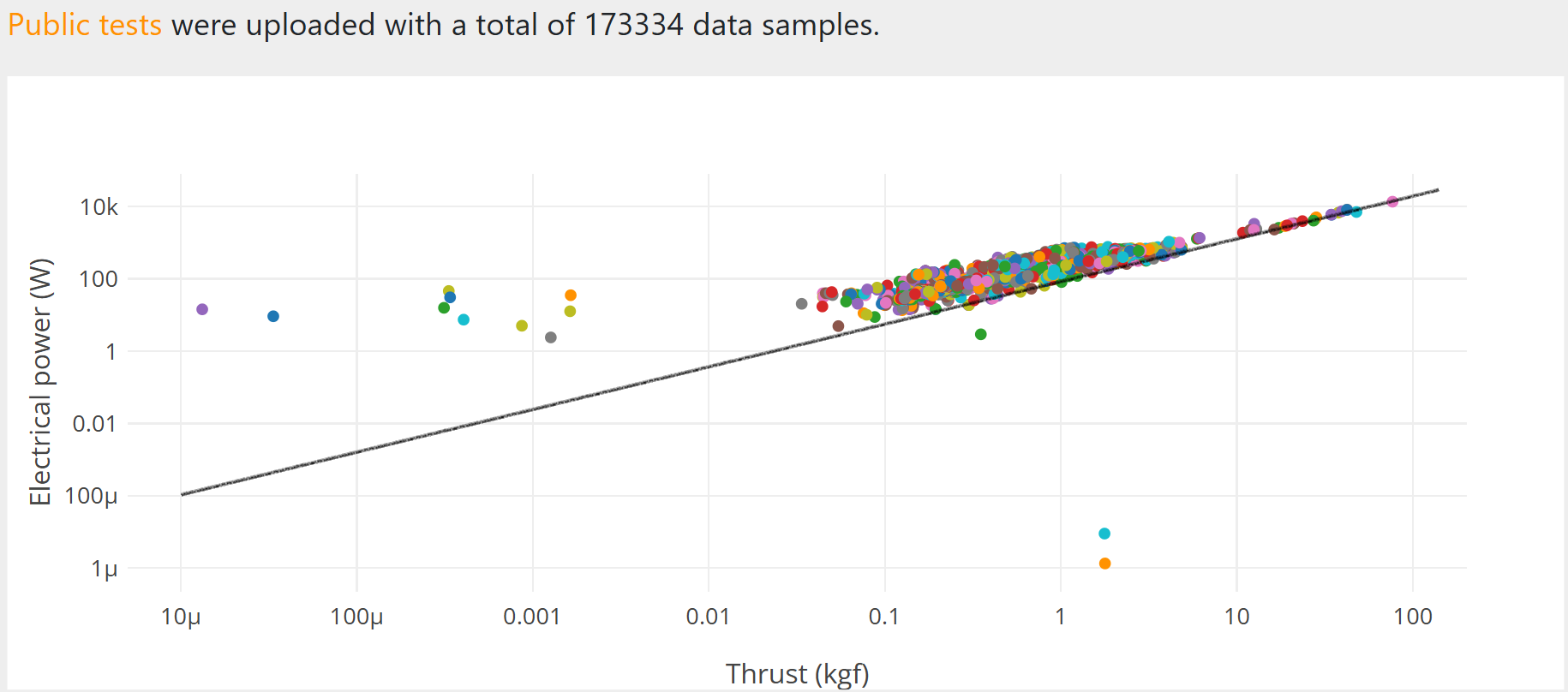
If we assume four lift fans per meter, and that each meter of tube weighs 336kg plus 100 kg for the pylons, gimballed motors, and propellers, then each lift fan would need to produce support 436/4=109 kg of thrust. From the image above, we can determine that the power per fan will be roughly 11 kW. This gives us a power-per-unit-thrust of 11,000/(109*9.81)=10.28 W/N.
The total power requirements will depend on which power-over-thrust value we use. The entire elevated evacuated tube is 102.4 km in length, so its total mass will be 436*102400 = 44.6 million kg. The power needed to keep it aloft will be between 0.5 to 2.2 GW.
Recirculating Vortices
A potential concern arises when considering the operation of the lift fans under stationary hover conditions. In still air, a vertically oriented fan can draw its own wake back into the flow, forming a recirculating vortex structure. This behavior is well documented in rotorcraft and is associated with reduced lift, since less of the airflow contributes to net downward momentum.
At a first level, this is a reasonable concern if the surrounding air were completely still and the flow were allowed to settle into a steady pattern. The key question is whether those conditions are likely to persist in practice.
In reality, the atmosphere is rarely motionless over the relevant length and time scales. Even modest prevailing winds introduce lateral motion that breaks the symmetry needed for a stable recirculating flow. Instead of forming a closed vortex, the wake is carried downstream, which prevents the fan from continuously re-ingesting its own flow. Observations from hovering rotorcraft and large fan systems suggest that relatively low crosswind speeds are often sufficient to disrupt these recirculation effects.
The system can also address this through control. The lift fans do not need to remain fixed in orientation. Small, continuous adjustments to the direction of thrust, or coordinated variations across multiple fans, can disrupt any developing flow structure before it becomes stable. This keeps the wake unsteady and prevents the formation of a persistent vortex that would degrade lift.
Taken together, this suggests that while recirculating flow in perfectly still air is a valid edge case, it is unlikely to define real-world performance. Ambient wind conditions and straightforward control approaches both act to keep the system operating outside regimes where lift would be significantly reduced. When estimating average power consumption, a recirculating flow is not assumed; however, the system's peak performance is specified to ensure sufficient power and lift to handle this edge case.
Electrical power is delivered from the ground through HVDC conductors sized according to:
where is the line voltage and the allowable current density. Using , , and , the resulting conductor area is , and the aluminum conductor mass per meter (with tapering and dual lines) is:
Even when including insulation and structural supports, the cable mass remains negligible compared to the tube mass.
Conversion from 600 kV to a voltage acceptable to the inverters and electric motors that drive the lift fans is achieved by wiring many motor-inverter systems in series between the HVDC lines. For example, if 800 V-class DC motors and inverters are used, as in modern electric vehicles, then the voltage can be down-converted by wiring motor-inverter systems in series.
In summary, the Elevated Evacuated Tube provides a mechanically efficient, electrically supported platform that extends the zero-drag corridor to an altitude of 15 km. Its structural mass per meter is on the order of 430 kg, its lift requirement is roughly 4.2 kN/m, and its power draw is approximately 44 kW/m at operating altitude. HVDC transmission from the ground minimizes onboard mass and energy storage needs, enabling sustained operation without propellant or consumables.

A camera drone filming the summit of Mt Everest, where the air density is roughly one-third what it is at sea level
Reviews
The following reviews are limited in scope to the validity of the claim made above, and do not imply that the reviewer has taken a position regarding any other claim or the overall feasibility of a concept that is supported by this claim.
- 1
 Reputation: 0Verdict: Supports
“I initially had several technical concerns about the claim. They're discussed in the review below, but after discussions with Phil and some edits to the claim, I now support it.”
Overview
The idea of an evacuated "tunnel in the sky" through which catapult-launched payloads could transit the denser layers of the atmosphere is intriguing. It might even be feasible. However, the evidence presented in support of the claim as it was initiall written had several flaws that needed to be addressed before I could support the claim. Specifically:
- The power-to-lift model assumed for lift fans / helicopter style rotors was too simplistic. It didn't account for potentially severe loss of lift when hovering in calm air far from the surface;
- Complications from the large dynamic range of air densities over which individual lift fans must operate when raising the evacuated tube from ground level to operational altitude were not addressed;
- The magnitude and speed of variations in lateral and vertical forces on the tube from high altitude wind turbulence and the ability of lift fans to compensate were not addressed;
- The need to down-convert HVDC to a power voltage that can be handled by the electric motors of the lift fans was not addressed. That turned out to have an easy solution, however. The power control units for the lift motors can be designed to operate in a manner that allows them to be connected in series.
Power-to-lift ratio
Regarding the power-to-lift model, the tight clustering of the data points along a straight line is misleading. It suggests that there is something fundamental about the roughly 10 to 11 W/N to which the line corresponds. That's not the case. The nominal power to lift ratio of lift fan or helicopter rotor is determined by two factors: the disk loading and air density. The general formula is
where total thrust (lift), air density, and swept disk area. \
is the "ideal" power for an ideal rotor; it's often increased by a factor of 1.2 - 1.5 to account for tip losses and air drag.
Note the dependence of P on the inverse of the square root of the air density times the swept area of the rotor. The air density at 15 km (exit altitude for the evacuated tube) is , vs at 4 km (the exit altitude for the up ramp). That's a ratio of . The square root is , whose inverse is . It therefore takes slightly over twice the power to produce the same lift at 15 km as it does at 4 km. However, by doubling the length of the rotor, the power at 15 k, can be roughly the same as for the smaller rotor at 4 km. It does mean that the larger rotor optimized for operation at high altitude will be turning half as fast at twice the motor torque when the tube is being deployed, but that's probably not a significant problem.
Unfortunately, there's another problem that is not so easily dismissed. The formula for power vs. lift implicitly assumes that the air being acted upon by the rotor has no (vertical) component of velocity before being drawn in by the rotor. That will be the case when the rotor is operating near the ground, in forward flight, or hovering above a fixed ground position in a substantial wind. It will not be the case when the rotor is hovering at altitude in calm air. It that situation, there will be a rapid buildup of a large self-generated ring vortex in the air around the rotor, with the rotor and its lift payload at the center of the vortex. The rotor will be fighting its own descending downwash, effectively having to "climb" faster and faster to stay in. place.
Most of the time, the problem of a stationary ring vortex building up around a helicopter or drone won't arise. There will be enough natural wind at the hover position to blow the ring vortex away and keep the rotor supplide with an adequate volume of "fresh" air for the rotor to push against. Or, if the helicopter or drone has freedom of movement, it can create a sustaining "wind" simply by moving. But for a rotor attached to a structure and required to hold that structure in a fixed position, the problem can and will arise whenever the air around the supported structure happens to be still.
Potential workaround
There is a potentially feasible feasible solution to this problem, albeit one that complicates the system design. The evacuated tube can be equipped with substantially more lift fans along its length than would otherwise be needed to support its weight. At any given moment, a subset of the lift fans sufficient to support the tube is powered on. The subset of active lift fans is a moving subset. It ripples along the length of the tube, simulating a fixed set of lift fans moving rapidly down the length of the tube. The sequencing of active lift fans is easy for control software to manage, and the weight penalty from the excess number of lift fans should be modest. However, when the lift fans are operating in this mode, there will be changing subsections of the tube that are under-supported, alternating with subsections that are over-supported. The tube must have sufficient strength and rigidity that the over-supported subsections can carry the weight of the under-supported sections. And since the over-supported and under-supported subsections are constantly changing, the control software needs to account for the possibility of mechanical resonances and material fatigue in the tube. It's not an unsolvable problem, but it will require careful design and thorough testing and verification to prove safety.
Power distribution
The use of HVDC to distribute power from the ground to the lift fans along the length of the evacuated tube is almost certainly not feasible, if the fan motors control units are connected in parallel. The problem is voltage conversion.
It is not possible to power an electric motor of any sort directly from 600 kV. The most advanced motor controllers for electric vehicles operate from an input voltage of ~1000 V. A 600 kV feed would need to be down-converted to 1000 V before it could be used to power the lift fans. But down-converters of that sort have very large footprints. According to Google's AI search engine, the connected elements of a 100 MW down-converter for an HVDC power line typically occupy a volume around a million cubic meters. Most of that volume will be air, but it's air supporting high tension electric fields and high strength magnetic fields. Attempting to compress the converter into a more compact volume will lead to arcing and catastrophic breakdowns.
One way around this problem would be the use of high temperature superconducting cables to distribute power at a voltage that EV-style motor controllers can handle. There is ongoing work to develop long distance superconducting power transmission lines, but at present, they remain too expensive for commercial deployment.
Another way around the problem would be to connect the power control units for all of the lift fans in series. That would mean that all the units would draw the same current, since the outpur current from one unit would be the input current to the next unit in line. They power from each unit could still be individually controlled, however, by allowing for a variable voltage drop across each unit. That differs from the conventional design for EV motor control units, but it's not inherently more complex or more difficult to implement.
Submitted: · Edited: