Claim
Launch Train Mass Target of ~39,000 kg is Achievable
Evidence
The Launch Train consists of three components: the fueled and loaded spacecraft, the launch sled, and the adaptive nut. The spacecraft mass is addressed in the separate claim entitled "Spacecraft Mass Target of ~28,000 kg is Achievable". This claim asserts that the launch sled can be ~1,000 kg, and the adaptive nut can be ~10,000 kg.
The launch sled magnetically couples the spacecraft to the guideway. At the beginning of horizontal acceleration it must support the combined mass of the spacecraft and sled, totaling 29,000 kg, under one Earth gravity of downward acceleration. Because the horizontal acceleration section follows the curvature of the Earth, the launch train experiences increasing upward centripetal acceleration as its speed increases. This upward acceleration progressively offsets the downward acceleration of gravity, and by the time the launch train reaches the ramp, centripetal acceleration dominates. During the 6.8-second ascent along the ramp, the train experiences 17.3 g of effective downward acceleration (see: The Upward Acceleration Target of 17.3 G's for 6.8 Seconds is Reasonable). Consequently, the launch sled must be capable of supporting a peak load of
which is equivalent to ~502 metric tons of force.
Let's first examine the possibility of supporting the sled using electromagnetic suspension (same technique used by Transrapid for the Shanghai maglev). In this system, the primary lifting electromagnets are situated below the T-shaped guideway as depicted in the figure below (note: only the cores of the primary lifting magnets are shown).
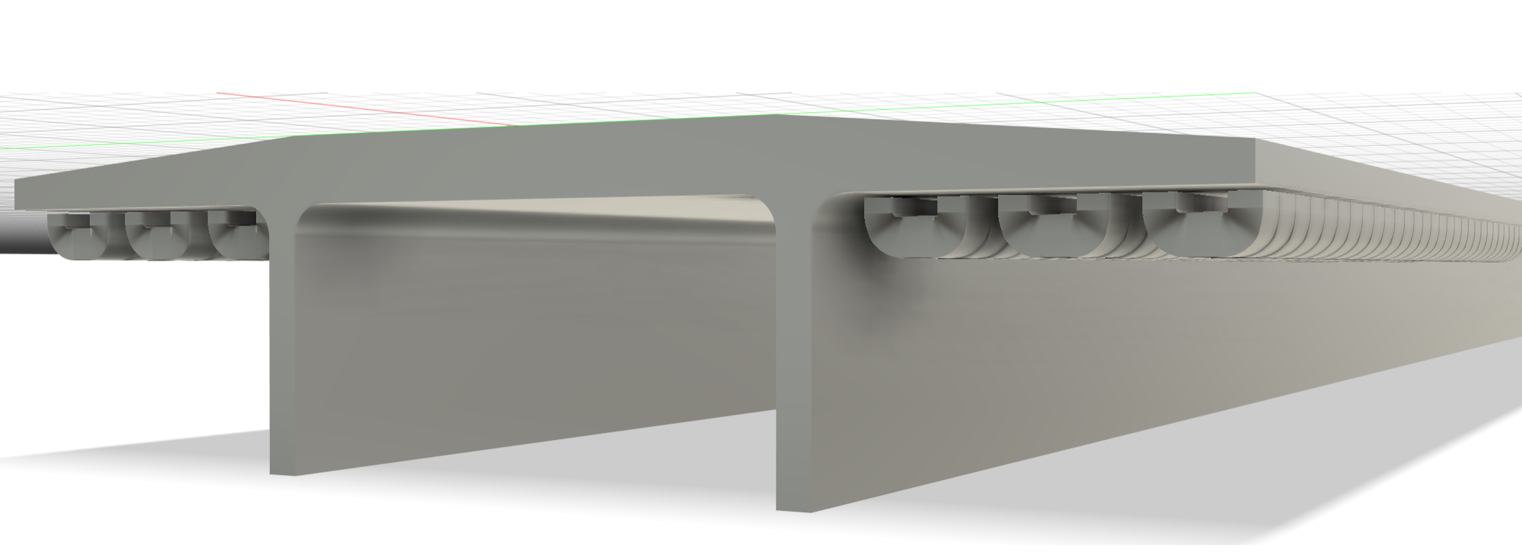
If the sled is 10 m in length, and the combined effective width of the magnetic airgaps is 0.48 m (0.24 m on each side of the guideway, 40mm per pole), then the total airgap area is
Using the standard relation between magnetic field strength and force generated across an airgap,
the required magnetic field in the gap is
A magnetic field of approximately 1.14 T is well below the saturation flux density of commonly used magnetic steels (2.1–2.4 T), indicating that the required force can be generated using standard electromagnet technology that is widely understood and commercially available.
The electromagnets will need to be oriented in a homopolar configuration to minimize eddy currents in the guideway, and the magnetic field strength can be engineered to gradually ease in and ease out along the length of the launch train to further reduce losses.
Each electromagnet's core, obtained from the CAD model that generated the figure above, masses 4.435 kg. There are 6 x 125 such magnets along the 10m length of the launch sled, or 6x125x4.435 kg = 3326.25 kg for just the magnet cores. This suggests that electromagnetic suspension might not be the best choice given the 1000 kg mass budget that we selected for the launch sled.
According to this article, EMS systems consume 3-5 kW of power per metric ton of train weight. This implies that the system could consume as much as (~3,700 horsepower) of power for the 6.8 seconds that the spacecraft and launch sled are on the ramp. This is a lot of power for a 1-ton machine, although perhaps possible give the progress that industry has made with fast charging of EV batteries, which routinely achieve 350 kW.
Another maglev technology, used in Japan’s SCMaglev (JR Central’s L0 Series) makes use of a repulsive technique called electrodynamic suspension (EDS). In this approach, the train carries superconducting magnets on its bogies, and the guideway walls contain passive coils (often wound in a “figure-8” configuration). As the vehicle moves, the changing magnetic field from the onboard superconducting magnets induces currents in these guideway coils. Those induced currents, by Lenz’s law, generate magnetic fields that oppose the change in flux and therefore repel the onboard magnets, producing both levitation and guidance forces without any active power electronics in the guideway.
EDS has some disadvantages relative to a purely electromagnetic suspension (EMS) system. First, it requires superconducting magnets on the vehicle, which implies cryostats, cryocoolers, and associated support hardware. This increases system complexity and introduces additional failure modes. Second, EDS requires passive levitation and guidance coils embedded along the guideway—L-shaped or figure-8 coils running the full length of the track—which increase the cost and complexity of the guideway relative to a simple ferromagnetic rail. Third, the system requires forward motion to generate levitation, which means that at low speeds a secondary system, such as EMS or auxiliary wheels, will be needed. Fourth, the system does generate some magnetic drag - although public technical information on SCMaglev's magnetic drag has yet to be discovered.
Some potential advantages of EDS are:
- Potentially the magnets on the sled could be lighter - although this is as yet unverified,
- It likely will support a large pole-to-track gap between the sled and the guideway, which could reduce the cost of achieving the guideway's straightness requirement, and
- The repulsive levitation forces are inherently self-stabilizing at high speed, reducing the burden on the active control system compared to EMS systems that must continuously regulate a small (millimeter-scale) airgap. Because levitation is passive no sensors and control circuits to achieve Earnshaw stability.
EDS technology will be used in the Chūō Shinkansen rail line between Tokyo and Nagoya, Japan, and it has amassed over 2,044,000 miles of test runs on test tracks such as the 42.8 km Yamanashi maglev test line.

A third technology, called "Inductrack" was developed at Lawrence Livermore National Laboratory under NASA sponsorship to demonstrate the acceleration rates and speeds needed to magnetically launch rockets. More technical information has been published about this technology.

Inductrack's time-averaged lift () and drag () forces per circuit (from Post & Dyutov) are given by
where
- , where is the wavelength of the Halbach array field
- ( is the vehicle speed)
- = inductance per track circuit (self + mutual)
- = resistance per track circuit
- = peak magnetic field at the surface of the Halbach array
- = transverse width of the Halbach array (m)
- = distance from the lower surface of the Halbach array to the centroid of the upper conductor leg of the track circuit (m)
Dividing (3) by (4) gives the lift-to-drag ratio:
Equation 9 in the paper shows how the ratio of weight levitated to weight of the magnets can be calculated. Here we assume and .
Thus, if we assume that the weight levitated is , and that half of the sled's mass is in its magnets, then
Rearranging and solving with we get
If these estimates bare out in practice, then it might be possible to replace the launch sled with retractable maglev skis that would stay with the space craft. While this would increase the cost of the spacecraft slightly (), eliminating sled recovery would significantly reduce the complexity of the launch system. Furthermore, if spacecraft are being sent in support of a base on The Moon or Mars, the magnets could be recycled and put to use in electric machinery upon arrival.
The mass budget for adaptive nut, which couples to both the screws and the guideway,
Reviews
The following reviews are limited in scope to the validity of the claim made above, and do not imply that the reviewer has taken a position regarding any other claim or the overall feasibility of a concept that is supported by this claim.
No reviews yet.