Claim
The Targeted Screw Flight Tip Velocity of 525 m/s is Attainable
Evidence
This claim asserts that the screw flights along the entire length of the acceleration and deceleration sections can safely operate with a tangential (tip) speed of 525 m/s. This refers to the local surface speed at the flight tip radius, not the vehicle speed. The vehicle's speed at any given position is computed by multiplying the tip velocity by the screw's pitch at that position.
Comparable Technologies
The tips of the fan blades in modern airliners jet engines move at speeds on the order of 500 m/s. High-speed steel rotors in centrifuges and turbomachinery routinely operate with peripheral speeds in the ~300–500 m/s range, and composite flywheels exceed that. VPSL’s 525 m/s target is of the same order as established high-speed rotating systems. The screws operate in vacuum on magnetic bearings and thus avoid aero loads at speed.
Engineering Specifics
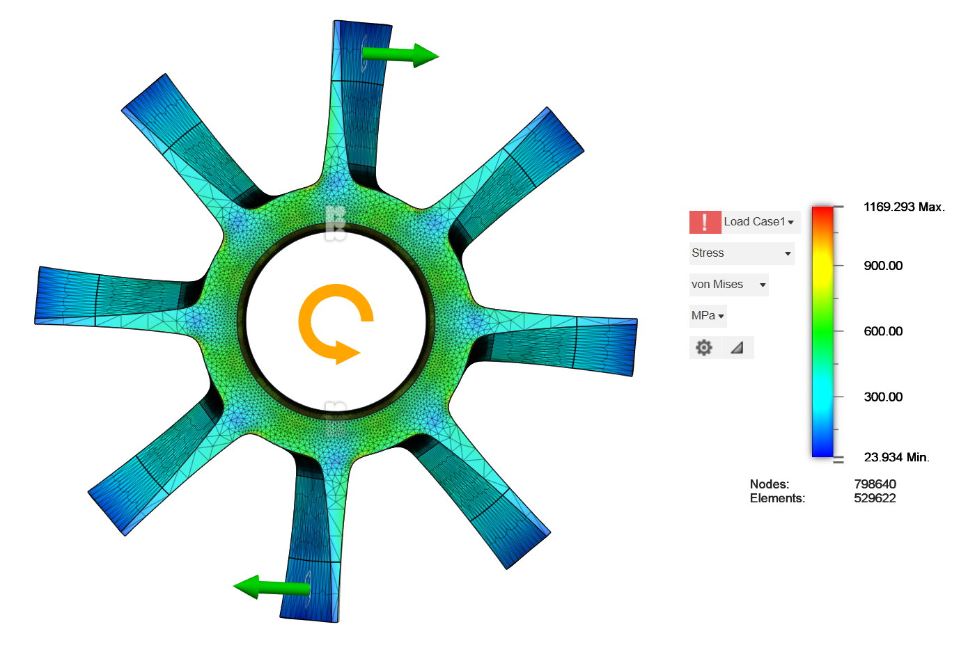
A screw segment from a high-pitch position was is described in the section entitled "F. Linear Active Magnetic Bearings (AMBs)" of this paper. Figure 13 shows the results of a simple stress simulation for a muzzle-end screw segment with eight starts (sets of flights). The simulation estimates the maximum tip speed given a set of input parameters. In this case an engineering factor of 1.5 was applied. The inner radius is 0.15 m and the radius to the tips of the screw flights is 0.5 m. The theoretical maximum tip speed is estimated to be 530 m/s. The material used for this simulation was A514 steel (T-1 high-strength) with a yield strength of 690 MPa, which is a high-strength, quenched and tempered alloy steel known for its excellent toughness and weldability. It is commonly used in heavy-duty structural applications like bridge construction, buildings, and machinery.
With higher-strength steels (e.g., maraging), feasible limits approach ~1000 m/s (with cost/complexity trade-offs). Even higher speeds might be possible with other metals or composites, but then the challenge of bonding a ferromagnetic material would increase leading to higher manufacturing costs.
The investigation also confirmed that the additional lateral loads fall well within the stress limits of the design. Figure 15 shows the lateral load-induced stresses only, and reveals that these stresses (up to 161 MPa) are small compared to the stresses caused by centrifugal forces (~1500 MPa).
Back-of-the-Envelope Check
A thin-ring estimate applies to the shaft and gives intuition for plausibility. For density ρ and allowable tangential stress σ_allow, the peripheral speed scales roughly as:
v_max ≈ sqrt(σ_allow / ρ)
For A514 steel with σ_allow ≈ 690 MPa/1.5, ρ ≈ 7850 kg/m³, and an engineering factor of 1.5:
v_max ≈ sqrt(690e6 / 1.5 / 7850) ≈ 242 m/s
The screw flight tip radius is roughly 2.25 times the shaft outer radius, so the tip speed is 242*2.25 = 544 m/s.
Other considerations
The screws operate within a temperature-controlled, evacuated environment, where they are not exposed to significant thermal cycling, oxidation, or high-cycle fatigue. In most terrestrial applications, metal alloys are formulated to balance competing properties such as strength, ductility, toughness, and corrosion resistance. In the controlled environment of the launch system, however, these trade-offs shift substantially. Because corrosion and large temperature swings are largely eliminated, the alloy composition and heat treatment can be optimized primarily for static and fatigue strength, even if this entails reduced ductility or corrosion resistance relative to conventional structural alloys. The analysis above assumes that commercially available metals are used in the screw's construction, and does not account for the additional gains that could be made with custom-engineered alloys.
See Also This video on YouTube claims to have spun a 3" diameter aluminum skateboard wheel up to 100,000 RPM with a waterjet, which is equivalent to a rim speed of 400 m/s (but not 8829 mph, or 3947 m/s as was claimed in the video).
Reviews
The following reviews are limited in scope to the validity of the claim made above, and do not imply that the reviewer has taken a position regarding any other claim or the overall feasibility of a concept that is supported by this claim.
- 0Verdict: Supports
“525 m/s can be achieved, but not with A514 steel and not with the illustrated screw shape.”
I wish this system allowed for a verdict of "qualified support". The binary "support / challenge" verdict is too restrictive. In the.present case, for instance, a screw flight tip velocity of can definitely be achieved, but not using the suggested A514 steel and the illustrated screw shape. So it's partly right but also wrong.
In the claim, the thin ring estimation method is used (correctly) to derive a of for the maximum safe velocity of the screw shaft. The approximate ratio between the radius of the shaft and the radius of the screw tip is then used to extrapolate a flight tip velocity in excess of . That implicitly assumes that the spinning screw flights are either massless and add no centrifugal stress to the shaft, or that tensile stress in the spiral screw flights are able to withstand the high centrifugal forces acting on the spinning screw flights on their own. The latter is possible, but only if the screw flights have a sufficiently high specific tensile strength and their pitch is relatively low. In the VPSL system targeting earth escape velocity, the screw pitch becomes too high for tensile stress in the screw flight to be significant for countering centrifugal force.
Since the design sketched out in the claim won't support the targeted screw flight tip velocity, something else is needed. Options include the use of materials with higher specific strength than A514 steel, and / or a substantially different design approach.
The claim does mention that with higher strength steels, higher speeds would be feasible -- although with cost / complexity tradeoffs. The strongest practical bulk material today for fabricating the shaft and screw is maraging steel. High grade maraging steel has a yield strength of 2620 MPa and a density of 8200 kg/m^3. That's just under 4x the yield strength of high grade A514 steel at about 3% higher density. That means that its v_max for the thin ring estimation would be a bit less than double that of A514 steel, around 480 m/s. That's close to, but still shy of the target 525 m/s.
The claim does mention that with higher strength steels, higher speeds would be feasible -- although with cost / complexity tradeoffs. That's true. The strongest practical bulk material today for fabricating the shaft and screw is maraging steel. High grade maraging steel has a yield strength of 2620 MPa and a density of 8200 kg/m^3. That's just under 4x the yield strength of high grade A514 steel and about 3% higher density. That means that its v_max for the thin ring estimation would be a bit less than double that of A514 steel, or around 480 m/s. That's close to, but still shy of the target 525 m/s.
The fact that even high grade maraging steel can’t meet the 525 mps target under the thin ring model is not fatal to the claim. The thin ring model, with the screw shaft modeled as a thin-walled cylinder, is structurally inefficient. It wastes half of the strength of any isotropic material from which the shaft is constructed. The spin-induced stresses are entirely circumferential, while the radial stresses are zero. The fact that maraging steel gets close to the 525 mps target under that model means that it wouldn’t take much improvement in the model to make the target. As it happens, there’s ample room for improvement.
The ideal shape for maximum energy storage in a rotating mass is a Stadola disk. That’s a disk with a thickness profile that starts from an initial value at the rotational axis, and tapers with radial distance from the axis. It’s the 2-D counterpart of a tapered tether in a gravitational field. The taper is such that all points within the disk experience equal stress in both radial and tangential directions. The ideal Stadola disk theoretically has an infinite radius, though at any given rate of rotation, the profile topers to an impractical thinness by the point that the tangential velocity is three to four times what the material’s thin ring estimate would allow. But tangential velocity of 2x the thin ring estimat should be quite feasible.
For the VPSL screw, the optimal configuration for leveraging an isotropic structural material would be a relatively thin-walled outer tube of nearly the same diameter as the overall screw. The screw flights would be at most lightweight strips welded to the outer surface of the tube. The inside of the tube would be filled with an evenly spaced array of thin tapered disks, welded at their peripheries to the inner surface of the outer tube. The walls of the tube itself might be a kind of “metal cardboard”, with a corrugated layer sandwiched between thin inner and outer surface layers. The corrugations would provide longitudinal stiffness for the tube wall, bridging between successive reinforcing disks. Longitudinal stiffness is needed, because the tube wall will be spinning too fast for tangential stress in the tube walls to keep them from bursting. If access to the interior of the screw shaft is required – i.e., the shaft must be hollow – then the solid disks can have their central areas removed. The removal is not free, however. It does not reduce the overall mass of the screw. The material removed is material that was uniformly stressed in both radial and tangential directions, helping to resist centrifugal forces in the spinning scres. It must be replaced by twice its mass in added material around the inner circumference of the “washer” that resulted from cutting a hole in the center of the disk. The added mass has to compensate for the inward radial force that the central disk of material was previously providing, but it has to do so entirely through tangential stress. It can't employ the combination of radial and tangential stress that the central disk was providing before the hole was cut.
Submitted: · Edited:
