Claim
The Adaptive Nut's Mechatronics Can Adapt to the Changing Geometry of the Screws
Evidence
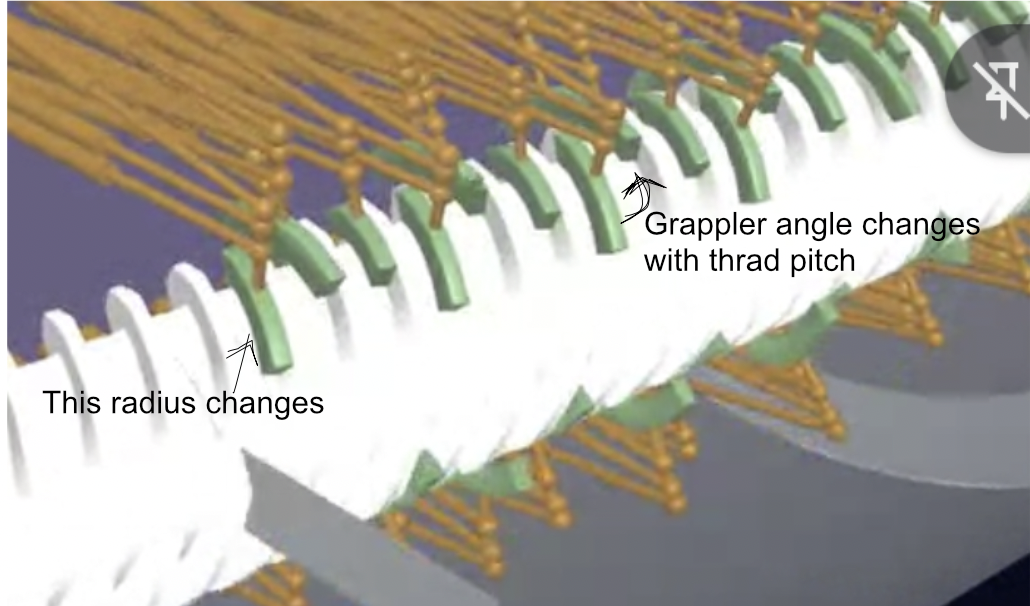
The Variable Pitch Screw Launch (VPSL) system can be understood as analogous to a nut driven along a rotating lead screw, with the key distinction that the screw’s pitch varies continuously along its length. As a result, a nut riding on the screw accelerates even when the screw rotates at constant angular speed. In the nut’s local frame of reference, the effective thread geometry therefore changes continuously during the run. To maintain proper engagement with the screw flights, the nut must present a correspondingly changing thread profile. This is achieved through a mechatronic system that actively adjusts the nut’s thread geometry to match the local pitch of the screw. An illustrative implementation of this concept is shown in this video.
At the beginning of the launch train’s acceleration, the screw pitch is relatively fine. Under these conditions, a vector normal to the screw’s thread face is oriented more closely in the direction of travel of the launch train. As the launch train accelerates and the screw pitch becomes progressively coarser, the normal vector to the thread face becomes increasingly inclined relative to the direction of travel. If the system is configured to maintain approximately constant acceleration, the magnitude of the forces normal to the thread face must therefore increase as the pitch becomes coarser.
The adaptive nut uses a mechatronic system to position grappler pads close to the screw flights. A continuous sequence of these pads forms a grappler pad strip, which follows a helical path conforming to the geometry of the screw flights.
The forces transmitted through the grappler pads can be decomposed into several components: a forward component that accelerates the launch train, and lateral and vertical components that must be resisted by the mechanical structure of the screws and their supporting brackets or by the magnetic levitation system that couples the adaptive nut to the guideway. To simplify the management of these reaction forces, several architectural features are incorporated, including: (a) twin counter-rotating screws, (b) screws with multiple thread starts, and (c) engagement of the adaptive nut with two or more opposing sets of screw flights.
This claim asserts that a mechatronic system can be developed that allows the grappler pads to adapt to the changing geometry of the screws as the local pitch varies along the guideway. To accomplish this, individual grappler pads must occasionally be repositioned as the relationship between the nut and the screw flights evolves during the launch run. The repositioning process involves temporarily disengaging a grappler pad, lifting it away from the screw flight, translating it outward so that it can clear the flight geometry, and then placing it near the face of a different screw flight before re-engaging it.
Algorithms within the digital twin have been developed to model one possible implementation of this repositioning process. Simulation videos show the sequence in operation and demonstrate that sufficient geometric clearance exists to perform these pad repositioning operations. Results from a full system simulation were included in the supplementary material submitted with the VPSL paper published in Transactions of Plasma Science.
Fully validating this concept will require additional engineering work on the adaptive nut’s mechatronic subsystem. The actuators must provide sufficient structural rigidity to withstand the dynamic loads present when a grappler pad is engaged with a screw flight, while also providing the speed and dexterity needed to occasionally reposition a pad. In addition, the total mass of the adaptive nut—which includes the maglev system, actuators, grappler pads, and associated power systems—must remain within its allocated mass budget. This claim therefore does not assert that the design is complete, but rather that the level of mechanical complexity required for the adaptive nut’s mechatronic system lies within the capabilities of modern mechatronic engineering.
Reviews
The following reviews are limited in scope to the validity of the claim made above, and do not imply that the reviewer has taken a position regarding any other claim or the overall feasibility of a concept that is supported by this claim.
- 1
“Partial Review - Control system can be devised, but mass is the challenge”
System Parameters Provided:
Thread rotational speed = 10,000 RPM
Thread Radius = .45 meters
Target Velocity = 11.2km/s
Accel = 8g where 1g is standard Earth 9.8m/s^2
System operates in a vacuum
Digital twin assumes 256 actuators
Disclaimer: All numbers here are preliminary sizing numbers for feasibility of the adaptive nut's thread tracking only.
Assumptions: This assessment does not address the grappler pads themselves, nor their power requirements; only geometric adjustments needed to align a grappler pad with a thread.
Preliminary validation of approximately 15lb for each 2000lbf actuator done via web search of industrial units.
The system operates in vacuum and we will ignore air resistance.
Length of track is not a concern for this portion of the concept.
Desired exit velocities range from 2.4km/s through 11.2km/s.
Power delivery is not addressed here.
Not all grapplers are engaged early on. (This could translate to slower actuator motion as fore/aft grapplers alternate 'grabbing' and 'releasing' during the rapid change of early thread pitch.
The configuration examined here is based on the linked video, although other strategies to adjust for thread pitch dynamically may exist, such as a snail-shell-shaped varying thread pitch wrapped around a cylinder, where the cylinder rotates to expose the correct thread pitch to the threaded shaft at all times through simple screw driven gear. (The main point being there may also be other approaches to the adaptive nut as well as this one.)
Actuator preliminary rough (napkin) calculations are done with the grappler at 12 o'clock or 6 o'clock positions for simplicity.
Actuator that manages grappler angle does not carry thrust loads. Actuator that manages grappler radius does not carry thrust loads.
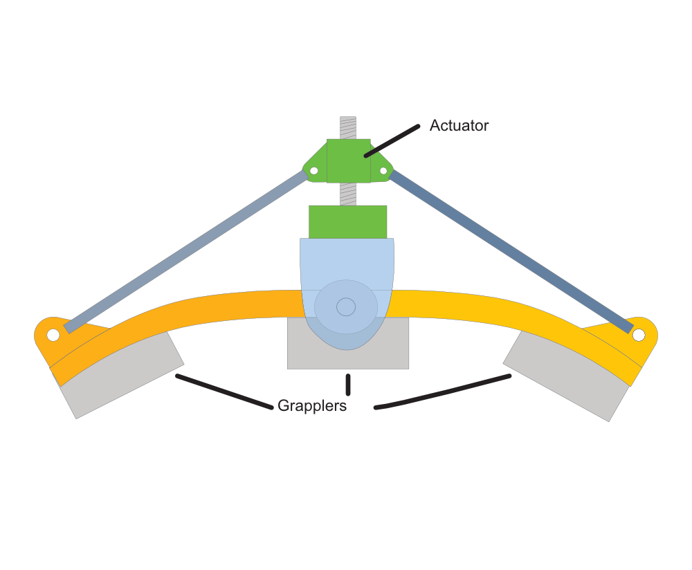
Primary position actuators in the "tripod" configuration are at approximately 20 degree angle to the force vector from the thread.
Actuators Required: There will likely be a total of 5 actuators to adjust for all degrees of freedom on the included video with an option for a 6th if the angle of the shoe relative to the normal surface of the threaded shaft must be actively controlled (this seems likely). All can likely be done with acme thread, ballscrew, or rollerscrew actuators with LVDT or similarly fine position feedback. Once position of the shoe in space, angle aside, is established, friction or serrated brakes may hold the actuator position.
1: The shoe will need to change effective radius unless it is narrow enough. As the thread becomes coarser and the grappler becomes more aligned with the threaded shaft, the effective radius of the grappler pad increases. There will need to be an actuator that increases and decreases that effective shoe radius. The load on this actuator should be fairly low. <100lbf
While crude, the sketch depicts a 'tent pole' actuator that lifts the leading and trailing ends of the grappler pad assuming they can be so subdivided, thereby adjusting its effective radius.
2: Alignment. The shoe will need to be aligned with the thread angle. This can be done with a fairly low power actuator that should be back-driveable because as the shoe no longer needs to lift off the thread later in the launch, it will need to rotate freely. The drag for this is not accounted for in this analysis.
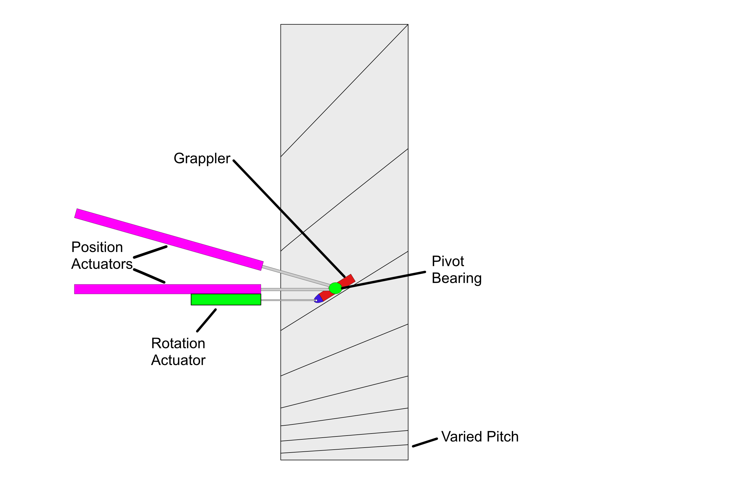
3,4,5: The main strut holding the shoe will need a lead/lag, lift/drop, and extend/retract actuator to adjust the position of the shoe in space. This would work as a sort of tripod similar to some coreXY 3D printers. Spread over 100 magnetic shoes, or 25 rows of 4 shoes, the lateral force at an accel of 8G is in the 380lbf range for 2.5km/s and 1700lbf for 11.2km/s after some rough math per screw. This can be accommodated by existing COTS electromechanical actuatiors.
NOTE: Depending on the design and attach points of the actuators to the grappler mount itself, it might be possible to manage grappler angle relative to the threaded shaft center line using the 3 primary load/position actuators.
6: An actuator that can be back-driven like the shoe-pitch actuator, but instead changes the angle of attack normal to the circumference of the threaded shaft. If a passive joint can be devised to always approach 'toes up' that works, this may be eliminated.
Rough Calculations:
Acceleration - 8g Final lateral load for 2.4km/s ~ 380lbf Final lateral load for 11.2km/s ~ 1600lbf Total mass of actuators without structure ~ 5100lbm for 256 actuators.
These are manageable loads with COTS actuators. Those actuators are likely to be in the 15lbm range, making the mass of actuators alone without structure approximately 3800lbm. There will be structure, not addressed here, and power and control systems, not addressed here.
I expect some additional torque to be required on the screws to keep the acceleration up.
Summary:
The loads on any single actuator are reasonable, and the mass of the actuators does not immediately cause a mass feedback loop that is insurmountable. If the rest of the adaptive nut's systems can be kept to low mass, then a payload may be accelerated in vacuum to the specified velocities. There are also opportunities for alternate configurations of the adaptive nut that may work. Levers that can be pulled for optimization include shaft RPM, target acceleration, and trading a smaller number of higher load grappler arms and actuators against the 256 arm configuration.
Submitted: · Edited:
