Work in progress: The author has indicated this claim is still being worked on and not yet ready for review.
Claim
The submerged acceleration tunnel can withstand launch-induced longitudinal forces without buckling.
Evidence
To help bound the analysis, let's first treat the entire 773.30 km acceleration section as a free-floating rigid body; then, for a train mass of 38,940 kg accelerating at 80 m/s², the reaction force would be
If the acceleration section mass is 7,710 kg/m, its total mass would be kg, and its backward acceleration would be . Over the approximately 139-second launch, it would acquire a backward velocity of 0.0726 m/s and move 5.05 m.
We can create a second boundary by setting the longitudinal rigidity to zero, so no forces are transmitted along the section. In this case, each location would be driven backward as the launch train passes.
In this limiting case, consider a short tube segment of length at position . Its mass is . The train passes it at speed , so the reaction force acts on that segment for approximately . Dividing the resulting backward impulse, , by the segment’s mass gives
In this limiting case, the start of the section is accelerated backward faster than the end of the section, so the overall effect is that accelerating the launch train causes the acceleration section to experience tension, never compression.
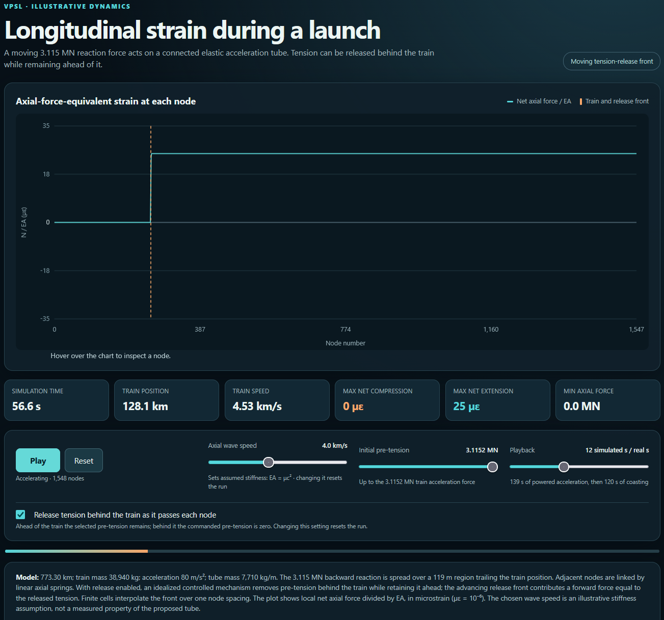
If we model the acceleration section as elastic, however, we observe many axial forces propagating as waves up and down the screws.
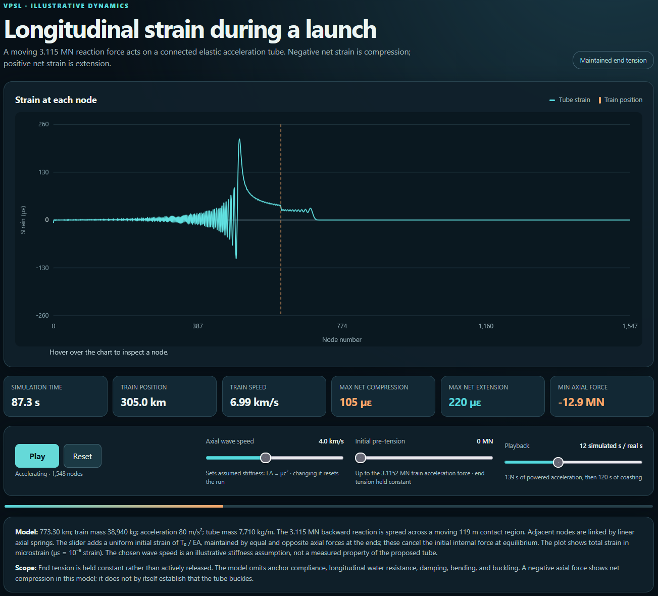
To prevent this, the entire launcher is pretensioned to the same force that is needed to accelerate the launch train forward. As the launch train advances down the launcher, this tension is released in screw segments that the launch train has passed by loosening geared coupling studs (see below) that attach the screw segments to one another.
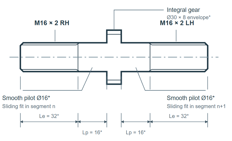
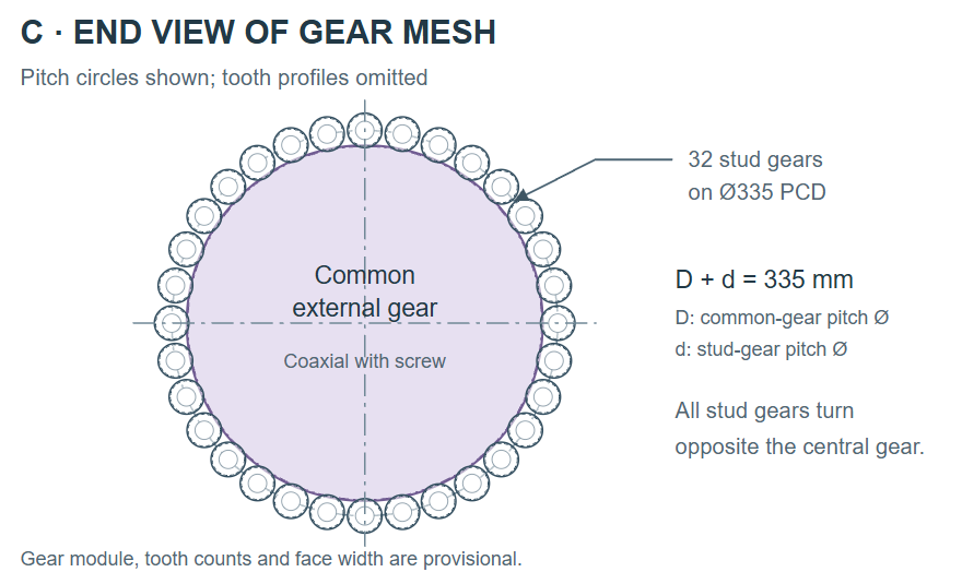
A master gear turns the studs' gears to rotate the studs, adjusting the gap between two coupled screw segments. The studs are loosened when the joint is lightly loaded, just as the accelerating launch train picks up the axial load. After launch, the studs are retightened to pretension the screws prior to the next launch.
Each screw carries half the acceleration force, shared by 32 coupling studs:
Assume steel with . The smooth stud sections have area , and the M16 threads have tensile area . Using 40 mm of smooth-equivalent length and half of each 32 mm threaded engagement as an approximate effective loaded length:
The extension of a 4,950 mm screw shaft, with inner radius 150 mm and outer radius 228 mm, is:
The opposite-hand threads each have 2 mm pitch, giving 4 mm of axial adjustment per revolution. Therefore:
Thus, approximately 46° of rotation per stud applies or releases the operating tension. Therefore, if it is not possible to engineer a master gear capable of generating the torque required to turn all the studs, the gears on the studs can be augmented by lever arms driven by a central rotating actuation ring through short connecting links. However, the master-gear concept is still preferred to facilitate system assembly.
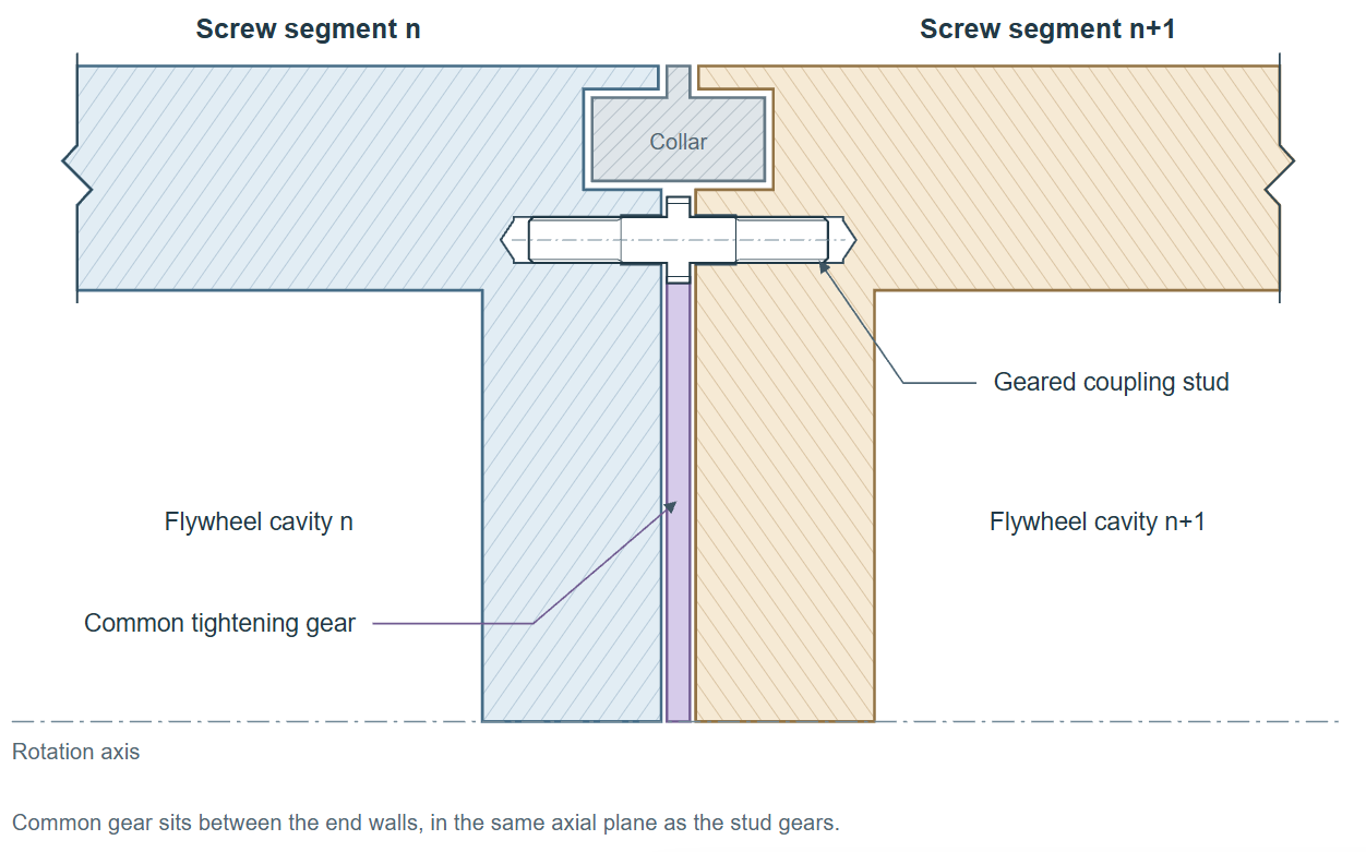
The use of pretensioning and synchronized release of that tension as the launch train advances eliminates the creation and propagation of longitudinal stress waves in the system.
Reviews
The following reviews are limited in scope to the validity of the claim made above, and do not imply that the reviewer has taken a position regarding any other claim or the overall feasibility of a concept that is supported by this claim.
No reviews yet.